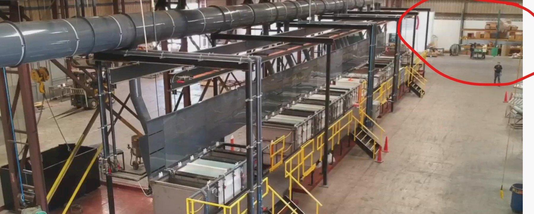
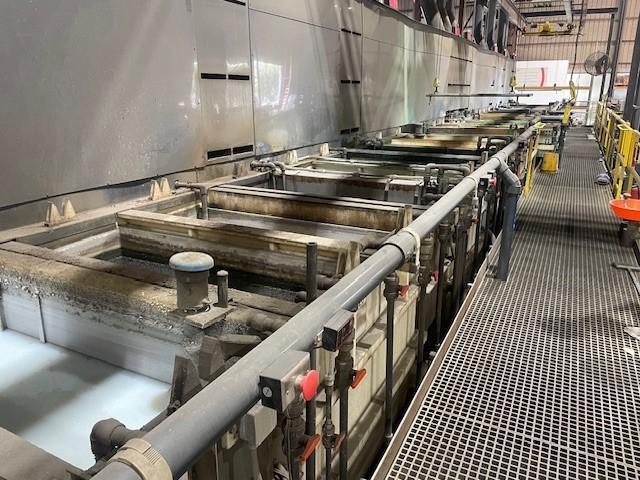
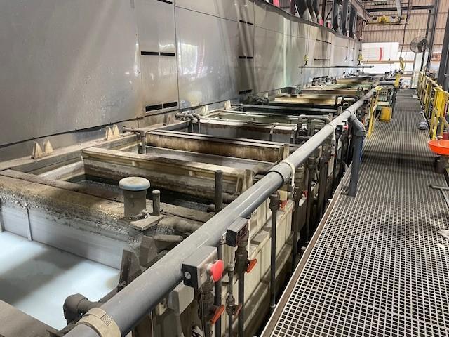
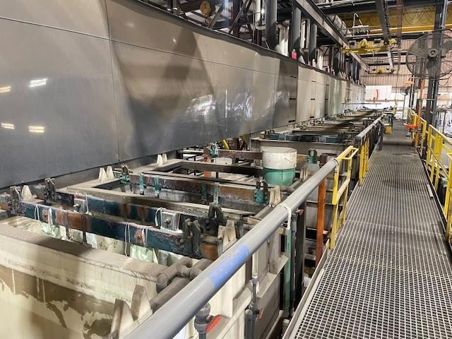
2019 CORROTEC ZINC NICKEL PROCESS PLATING LINE
Year
2019
Stock #
19436
Condition
Like New
Keep Scrolling To Learn More
Specifications
Equipped With
2019 CORROTEC ZINC NICKEL PROCESS PLATING LINE
New 2019
Like New
- 001- Plating Line Tanks
- 002- Plating Line Tanks
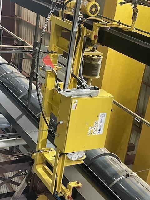
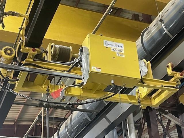
- 003 – Electrolift 3/4 ton crane (2 on line)
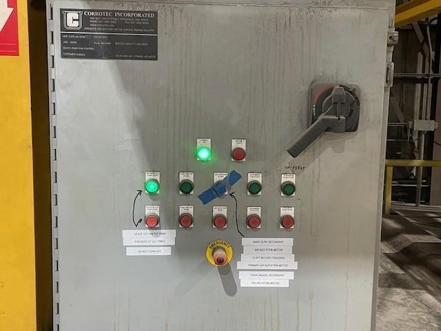
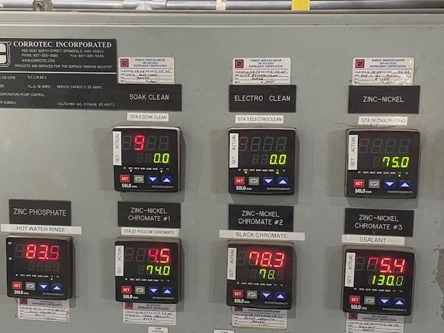
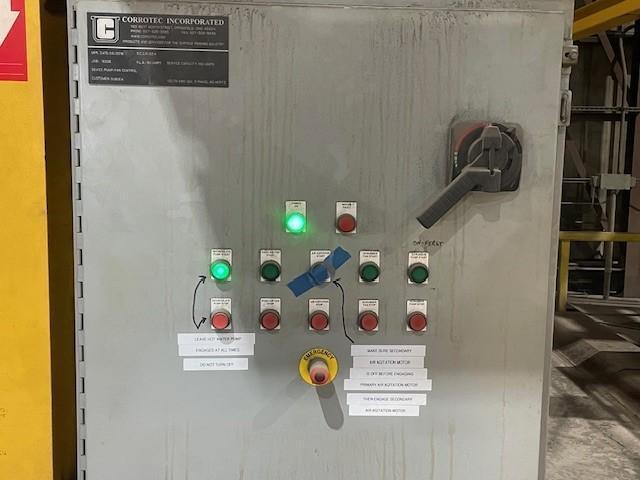
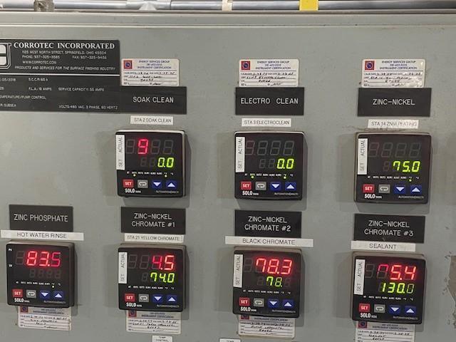
- 005 – Plating Tanks Control Box
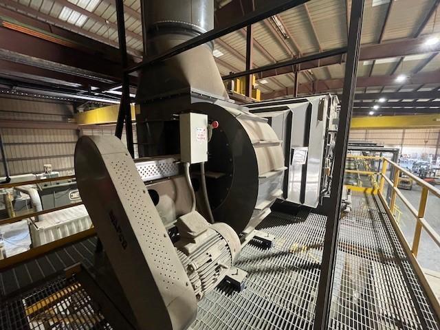
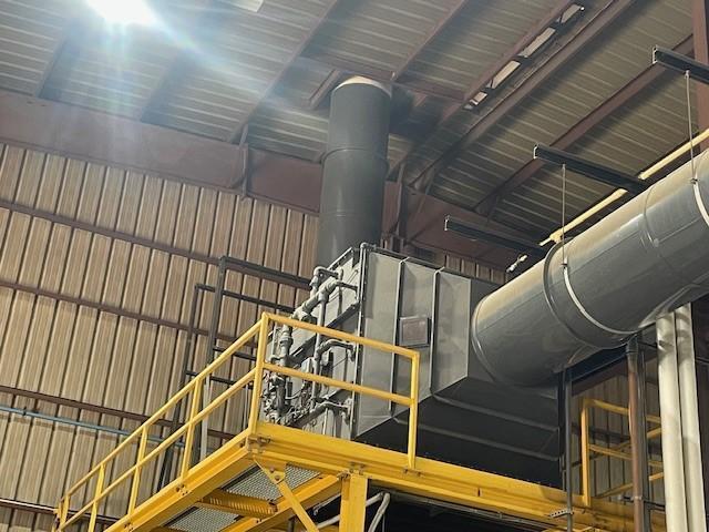
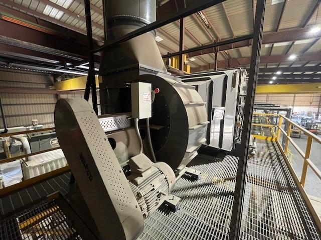
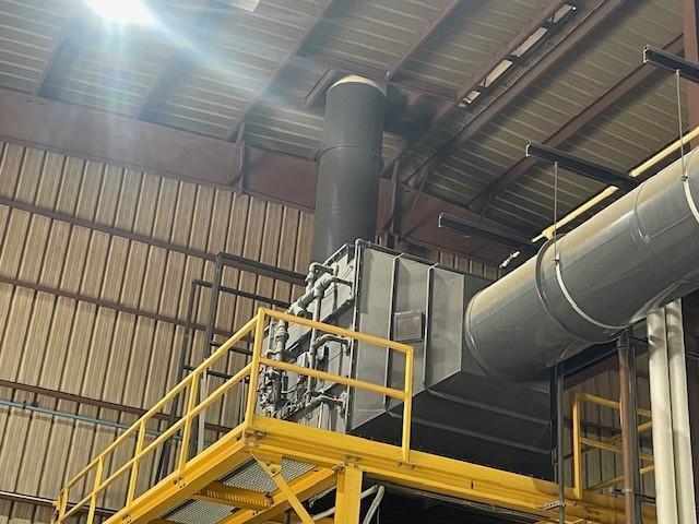
- 006 – MAPCO Air Scrubber
- 007 – Air Scrubber Control Box
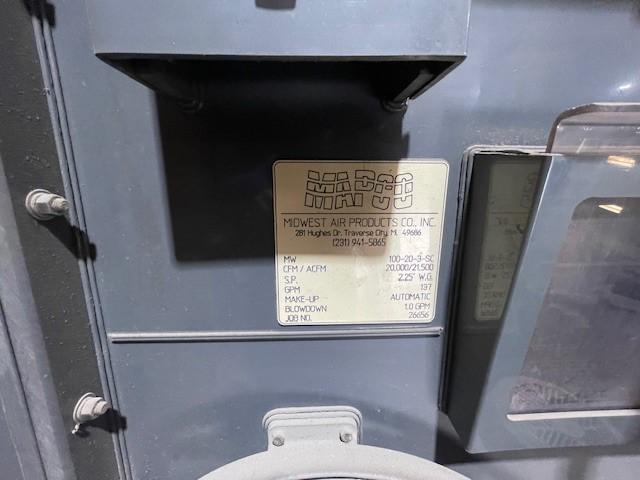
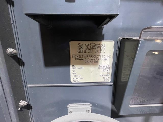
- 008 – MAPCO Air Scrubber
- 009 – MAPCO Air Scrubber Information Placard
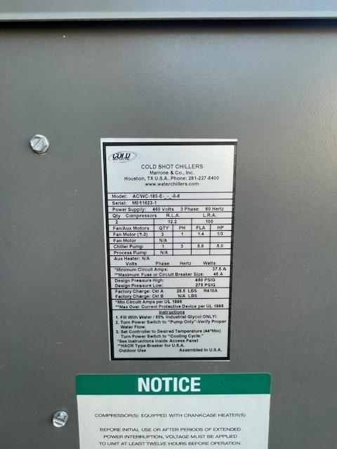
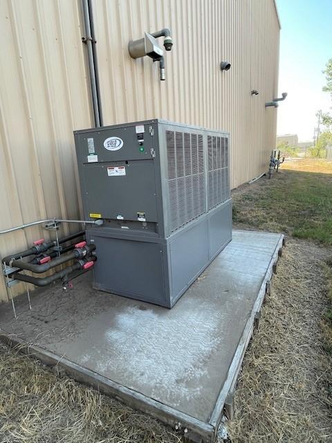
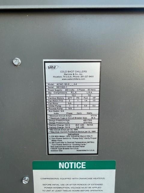
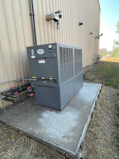
- 010 – Cold Shot Chiller
- 011 – Cold Shot Chiller Information Placard
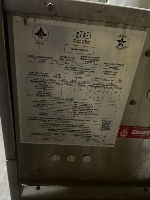
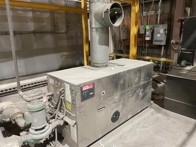
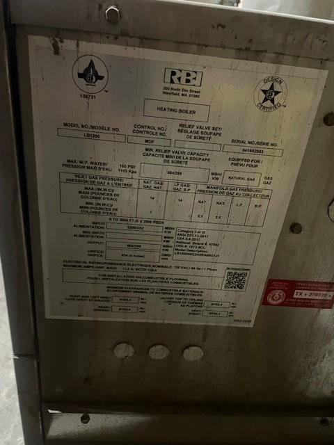
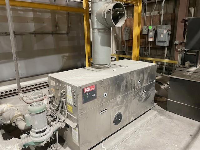
- 012 – RBI Boiler
- 013 – RBI Boiler Information Placard
PROCESS CYCLE
|
TANK # |
DESCRIPTION |
TEMPERATURE |
TIME |
|
|
|
|
|
|
1 |
Manual Load/Unload Station #1 |
--- |
--- |
|
|
|
|
|
|
2 |
Soak Clean |
1600F |
5-7 minutes |
|
|
|
|
|
|
3 |
Electroclean |
1600F |
5-7 minutes |
|
|
|
|
|
|
4-5 |
Counterflow Rinse |
--- |
--- |
|
|
|
|
|
|
6 |
Strip Tank |
Ambient |
As Required |
|
|
|
|
|
|
7-8 |
Counterflow Rinse |
--- |
--- |
|
|
|
|
|
|
9 |
Acid Pickle |
Ambient |
2-5 minutes |
|
|
|
|
|
|
10 |
FUTURE DESMUT |
--- |
--- |
|
|
|
|
|
|
11-12 |
FUTURE COUNTERFLOW RINSE |
--- |
--- |
|
|
|
|
|
|
13 |
Pre-Dip |
--- |
--- |
|
|
|
|
|
|
14-15 |
Acid Zinc-Nickel Plate (2-station) |
800F |
20 minutes |
|
|
|
|
|
|
16-17 |
Counterflow Rinse |
--- |
--- |
|
|
|
|
|
|
18 |
CART STATION |
|
|
|
|
|
|
|
|
19 |
Zinc-Nickel Plate Activate |
Ambient |
30 seconds |
|
|
|
|
|
|
20 |
Rinse |
--- |
--- |
|
|
|
|
|
|
21 |
Zinc-Nickel Chromate #1 |
800F |
1 minute |
|
|
|
|
|
|
22-23 |
Counterflow Rinse |
--- |
--- |
|
|
|
|
|
|
24 |
Zinc-Nickel Chromate #2 |
800F |
1 minute |
|
|
|
|
|
|
25-26 |
Counterflow Rinse |
--- |
--- |
|
|
|
|
|
|
27 |
Zinc-Nickel Chromate #3 |
800F |
1 minute |
|
|
|
|
|
|
28-29 |
Counterflow Rinse |
--- |
--- |
|
|
|
|
|
|
30 |
Seal |
Ambient |
1 minute |
|
|
|
|
|
|
31 |
FUTURE DRYER |
1500F |
10 minutes |
|
|
|
|
|
|
32 |
CART STATION |
|
|
|
|
|
|
|
|
33-A |
ZINC PHOSPHATE TANK |
1800F |
20 MINUTES |
|
|
|
|
|
|
34-35 |
COUNTERFLOW RINSE |
|
|
|
|
|
|
|
|
36 |
OIL |
AMBIENT |
1 MINUTE |
|
|
|
|
|
|
37 |
OIL DRIP |
|
|
HOIST & STRUCTURE
Type of Equipment: Manual Overhead Hoist System
Rack Size: 10” DOT x 50” FTB x 50” Tall
Load Capacity: 1,500 lbs.
Number of Hoists One (1)
Hoist Control System Manual Operation with Motorized Trolley
Drive System Variable Speed drive (0-35 fpm),
Lift System Variable Speed drive (0-25 fpm),
System Voltage 480 V, 60 HZ 3 PH
General Equipment Specifications
1.0 Structure
The proposed tank line requires a single-lane structure with an approximate 15’ wide x 114.5’ long footprint. The structure comes complete with all required bracing and supports.
2.0 Hoist
The Hoist and Structure will be:
• Fabricated using standard structural steel shapes;
• Prefabricated for shipment in sections,
• Self-supporting
• Designed with weight bearing capacity;
• Prepared and painted with a 2-part paint;
• One (1) 1,500 lb. Hoist
• Conductor Bar electrification
Capacity: 1,500 lb.
Runway Length: 114.5’
Structure Height 17’-6”
Structure Width: 15’
Hoist Lift: 15’ twin hook
Lift Speed: 25 FPM VFD
Pushbutton Drop: 10’
Power Supply: 480 volts/3-phase/60 Hz
3.0 Manual Docking Stations
· Three (3) load/unload stations with floor mounted guide rails to position the manual carts under the hoist rail. A cart locating, and locking mechanism is provided.
4.0 Load Carts: (3 required)
Heat-Up Time:
Four (4) hour with 190º F Hot Water Boiler
3. City Water:
40-60 PSI
1. All tanks are 62” front to back (FTB) x 64” deep with direction of travel (DOT) as specified.
2. All tanks are fabricated from 1” thick polypropylene, or 7-guage 316L Stainless Steel. (exceptions as noted).
3. All tanks have a rim and reinforcement girths as required.
4. All overflow outlets and bottom drains are 1-1/2” diameter.
5. All rinse tank overflows are 3” DOT x 6” x 62” FTB.
6. All rinse tank overflows are located on the inside of tank sidewalls.
7. All tanks have 1” diameter Schedule 80 PVC water fill piping with true union ball valve.
8. Tank line is outfitted with a drip shield between each tank.
9. All room temperature tanks with drains have 1-1/2” diameter PVC true union ball valves. All heated tanks with drains have 1-1/2” diameter CPVC true union ball valves.
10. All heated tanks have temperature controls.
11. All heated tanks are designed for a four (4) hour heat-up time.
12. All tanks with air agitation have 1” diameter air sparger with true union ball valve.
13. Each station comes equipped with two (2) locating saddle. Electroclean and plating tank have electrified saddles.
14. Exceptions where noted.
4. Compressed Air:
100 psi minimum
5. Natural Gas:
By Customer
6. Cooling Water:
450F Water – Plating Tanks
7. RO Water:
· Cart Size: 32” DOT x 62” F to B x 77” Tall
· Material of Construction: Mild Steel Frame/PPro Drip Tray
· Cart is blasted, primed and painted with two (2) coat safety orange paint
· Two (2) Non-electrified saddles
· Four (4) Casters (two swivel and two fixed)
STATION 1: MANUAL CART DOCKING STATION
§ Painted Steel. floor mounted guide rails to position the manual carts under the hoist rail.
§ Cart Size: 32” DOT x 62” FTB x 77” high
STATION 2: SOAKCLEAN
§ Polypropylene Tank Construction
§ Tank Size: 25” DOT x 62” FTB x 64” Deep
§ Tank Volume: 451 gallons (including front weir)
§ Temperature: 1600F
§ Front Overflow (25” DOT x 15” FTB x 30” Deep) with outlet
§ One (1) Recirculation Pump
§ Temperature controller
§ One (1) Level Control for low level pump protection
§ One (1) Ventilation hood
§ One (1) Manual water fill with ball valve
§ One (1) 1-1/2” diameter bottom drain
§ Two (2) Non-electrified saddles
STATION 3: ELECTROCLEAN
§ Polypropylene Tank Construction
§ Tank Size: 32” DOT x 62” FTB x 64” Deep
§ Tank Volume: 578 gallons (including front weir)
§ Temperature: 1600F
§ Front Overflow (32” DOT x 15” FTB x 30” Deep)
§ One (1) Recirculation Pump
§ One (1) Hot Water Coil
§ Temperature controller
§ One (1) Level Control for low level pump protection
§ One (1) Ventilation hood
§ One (1) Rectifier
§ Copper bussing for 1,500 amps
§ Two (2) submerged steel-bar grate cathodes
§ One (1) Manual water fill with ball valve
§ One (1) 1-1/2” diameter bottom drain
§ Two (2) Electrified saddles
STATION 4-5: COUNTERFLOW RINSE
§ Polypropylene Tank Construction
§ Tank Size: 52” DOT x 62” FTB x 64” Deep
§ Tank Volume: ---
§ Temperature: ---
§ Two (2) Single-leg PVC air spargers with ball valves
§ One (1) Over/Under Baffle
§ One (1) Overflow Weir with one (1) 1-1/2” drain
§ Two (2) Manual water fills with ball valves
§ One (1) Rotometer (.5-5 GPM)
§ Two (2) 1-1/2” diameter bottom drains
§ Four (4) Non-electrified saddles
STATION 6: STRIP TANK
§ Polypropylene Tank Construction
§ Tank Size: 26” DOT x 62” FTB x 64” Deep
§ Tank Volume: 403 gallons
§ Temperature: Ambient
§ One (1) Single-leg PVC air sparger with ball valve
§ One (1) Ventilation hood
§ One (1) Manual water fill with ball valve
§ One (1) 1-1/2” diameter bottom drain
§ Two (2) Non-electrified saddles
STATION 7-8: COUNTERFLOW RINSE
§ Polypropylene Tank Construction
§ Tank Size: 52” DOT x 62” FTB x 64” Deep
§ Tank Volume: ---
§ Temperature: ---
§ Two (2) Single-leg PVC air spargers with ball valves
§ One (1) Over/Under Baffle
§ One (1) Overflow Weir with one (1) 1-1/2” drain
§ Two (2) Manual water fills with ball valves
§ One (1) Rotometer (.5-5 GPM)
§ Two (2) 1-1/2” diameter bottom drains
§ Four (4) Non-electrified saddles
STATION 9: ACID PICKLE
§ Polypropylene Tank Construction
§ Tank Size: 25” DOT x 62” FTB x 64” Deep
§ Tank Volume: 403 gallons
§ Temperature: Ambient
§ One (1) Single-leg PVC air sparger with ball valve
§ One (1) Ventilation hood
§ One (1) Manual water fill with ball valve
§ One (1) 1-1/2” diameter bottom drain
§ Two (2) Non-electrified saddles
STATION 13: ZINC-NICKEL PRE-DIP
§ Polypropylene Tank Construction
§ Tank Size: 24” DOT x 62” FTB x 64” Deep
§ Tank Volume: 386
§ Temperature: Ambient
§ One (1) Single-leg PVC air sparger with ball valve
§ One (1) Manual water fill with ball valve
§ One (1) 1-1/2” diameter bottom drain
§ Two (2) Non-electrified saddles
STATION 14-15: ZINC-NICKEL PLATE (2-station)
§ Polypropylene Tank Construction
§ Tank Size: 94” DOT x 62” FTB x 64” Deep
§ Tank Volume: 1,516 gallons
§ Temperature: 800F
§ Front Overflow (94” DOT x 15” FTB x 23” Deep) with outlet
§ One (1) Recirculation Pump and Filter System with slurry
§ One (1) Titanium Hot Water Coil
§ One (1) Titanium cooling coil
§ Temperature controller
§ One (1) Level Control for low level pump protection
§ One (1) Ventilation hood
§ Two (2) Single-leg CPVC air sparger with ball valve
§ One (1) Rectifier – Zinc 1,500 amps
§ Copper bussing for 1,500 amps per station - Zinc
§ One (1) Rectifier – Nickel 500 amps
§ Copper bussing for 500 amps per station - Nickel
§ Slab zinc anodes (By Others)
§ Four (4) Titanium anode baskets -nickel anodes by others
§ One (1) Manual water fill with ball valve
§ One (1) 1-1/2” diameter bottom drain
§ Four (4) Electrified saddles
STATION 16-17: COUNTERFLOW RINSE
§ Polypropylene Tank Construction
§ Tank Size: 52” DOT x 62” FTB x 64” Deep
§ Tank Volume: ---
§ Temperature: ---
§ Two (2) Single-leg PVC air spargers with ball valves
§ One (1) Over/Under Baffle
§ One (1) Overflow Weir with one (1) 1-1/2” drain
§ Two (2) Manual water fills with ball valves
§ One (1) Rotometer (.5-5 GPM)
§ Two (2) 1-1/2” diameter bottom drains
§ Four (4) Non-electrified saddles
STATION 18: LOAD CART DOCKING STATION
v Docking Station (See Section III. Hoist & Structure)
STATION 19: ZINC-NICKEL ACTIVATE
§ Polypropylene Tank Construction
§ Tank Size: 24” DOT x 62” FTB x 64” Deep
§ Tank Volume: 386 gallons
§ Temperature: Ambient
§ One (1) Single-leg PVC air sparger with ball valve
§ One (1) Manual water fill with ball valve
§ One (1) 1-1/2” diameter bottom drain
§ Two (2) Non-electrified saddles
STATION 20: RINSE
§ Polypropylene Tank Construction
§ Tank Size: 24” DOT x 62” FTB x 64” Deep
§ Tank Volume: ---
§ Temperature: ---
§ One (1) Single-leg PVC air sparger with ball valve
§ One (1) Overflow Weir with one (1) 1-1/2” drain
§ One (1) Manual water fill with ball valve
§ One (1) Rotometer (.5-5 GPM)
§ One (1) 1-1/2” diameter bottom drain
§ Two (2) Non-electrified saddles
STATION 21: ZINC-NICKEL CHROMATE #1
§ 316L Stainless Steel Tank Construction
§ Tank Size: 25” DOT x 62” FTB x 64” Deep
§ Tank Volume: 403 gallons
§ One (1) Single-leg PVC air sparger with ball valve
§ One (1) Stainless Steel Hot Water Coil
§ Temperature controller
§ One (1) Ventilation hood
§ One (1) Single-leg CPVC air sparger with ball valve
§ One (1) 1-1/2” diameter bottom drain
§ One (1) Manual water fill with ball valve
§ Two (2) Non-electrified saddles
STATION 22-23: COUNTERFLOW RINSE
§ Polypropylene Tank Construction
§ Tank Size: 52” DOT x 62” FTB x 64” Deep
§ Tank Volume: ---
§ Temperature: ---
§ Two (2) Single-leg PVC air spargers with ball valves
§ One (1) Over/Under Baffle
§ One (1) Overflow Weir with one (1) 1-1/2” drain
§ Two (2) Manual water fills with ball valves
§ One (1) Rotometer (.5-5 GPM)
§ Two (2) 1-1/2” diameter bottom drains
§ Four (4) Non-electrified saddles
STATION 24: ZINC-NICKEL CHROMATE #2
§ 316L Stainless Steel Tank Construction
§ Tank Size: 25” DOT x 62” FTB x 64” Deep
§ Tank Volume: 403 gallons
§ Temperature: 800F
§ One (1) Single-leg PVC air sparger with ball valve
§ One (1) Stainless Steel Hot Water Coil
§ Temperature controller
§ One (1) Ventilation hood
§ One (1) Single-leg CPVC air sparger with ball valve
§ One (1) 1-1/2” diameter bottom drain
§ One (1) Manual water fill with ball valve
§ Two (2) Non-electrified saddles
STATION 25-26: COUNTERFLOW RINSE
§ Polypropylene Tank Construction
§ Tank Size: 52” DOT x 62” FTB x 64” Deep
§ Tank Volume: ---
§ Temperature: ---
§ Two (2) Single-leg PVC air spargers with ball valves
§ One (1) Over/Under Baffle
§ One (1) Overflow Weir with one (1) 1-1/2” drain
§ Two (2) Manual water fills with ball valves
§ One (1) Rotometer (.5-5 GPM)
§ Two (2) 1-1/2” diameter bottom drains
§ Four (4) Non-electrified saddles
STATION 27: ZINC-NICKEL CHROMATE #3
§ 316L Stainless Steel Tank Construction
§ Tank Size: 25” DOT x 62” FTB x 64” Deep
§ Tank Volume: 403 gallons
§ Temperature: 800F
§ One (1) Single-leg PVC air sparger with ball valve
§ One (1) Stainless Steel Hot Water Coil
§ Temperature controller
§ One (1) Ventilation hood
§ One (1) Single-leg CPVC air sparger with ball valve
§ One (1) 1-1/2” diameter bottom drain
§ One (1) Manual water fill with ball valve
§ Two (2) Non-electrified saddles
STATION 28-29: COUNTERFLOW RINSE
§ Polypropylene Tank Construction
§ Tank Size: 52” DOT x 62” FTB x 64” Deep
§ Tank Volume: ---
§ Temperature: ---
§ Two (2) Single-leg PVC air spargers with ball valves
§ One (1) Over/Under Baffle
§ One (1) Overflow Weir with one (1) 1-1/2” drain
§ Two (2) Manual water fills with ball valves
§ One (1) Rotometer (.5-5 GPM)
§ Two (2) 1-1/2” diameter bottom drains
§ Four (4) Non-electrified saddles
STATION 30: SEAL
§ 316L Stainless Steel Tank Construction
§ Tank Size: 25” DOT x 62” FTB x 64” Deep
§ Tank Volume: 403 gallons
§ Temperature: Ambient
§ One (1) 1-1/2” diameter bottom drain
§ One (1) Manual water fill with ball valve
§ Two (2) Non-electrified saddles
STATION 32: LOAD CART DOCKING STATION
v Docking Station (See Section III. Hoist & Structure)
STATION 33-A: ZINC PHOSPHATE
§ 316 Stainless Steel Tank Construction
§ Tank Size: 28” DOT x 62” FTB x 64” Deep
§ Tank Volume: 451 gallons
§ Temperature: 1800F
§ One (1) Hot Water Coil
§ Temperature controller
§ One (1) Ventilation hood
§ One (1) Manual water fill with ball valve
§ One (1) 1-1/2” diameter bottom drain
§ Two (2) Non-electrified saddles
STATION 34-35: COUNTERFLOW RINSE
§ Polypropylene Tank Construction
§ Tank Size: 52” DOT x 62” FTB x 64” Deep
§ Tank Volume: ---
§ Temperature: ---
§ Two (2) Single-leg PVC air spargers with ball valves
§ One (1) Over/Under Baffle
§ One (1) Overflow Weir with one (1) 1-1/2” drain
§ Two (2) Manual water fills with ball valves
§ One (1) Rotometer (.5-5 GPM)
§ Two (2) 1-1/2” diameter bottom drains
§ Four (4) Non-electrified saddles
STATION 36: OIL
§ 316L Stainless Steel Tank Construction
§ Tank Size: 25” DOT x 62” FTB x 64” Deep
§ Tank Volume: 386 gallons
§ Temperature: Ambient
§ One (1) 1-1/2” diameter bottom drain
§ One (1) Manual water fill with ball valve
§ Two (2) Non-electrified saddles
STATION 37: OIL DRIP STAND with PAN
§ Painted Steel Stand with locating saddles.
§ Size: 22” DOT x 62” FTB x64” height
§ ½” polypropylene pan 22” x 83” x 12” deep
Submersible pump to return oil to oil tank (Operator Controlled)
SECTION V. AUXILIARY EQUIPMENT
1. AUXILARY EQUIPMENT MOTOR CONTROL CABINET
§ Control cabinet(s) with fused disconnect, fuses, and control transformer (as required).
§ Process controls will be localized where possible
§ IEC motor starters with IEC rated disconnects for local control of equipment. Equipment will be distributed based on locations determined during the design phase of the project.
(Panel-1 480V 3PH 100 AMP)
o One (1) air agitation blower
o One (1) push air fan
o One (1) exhaust blower
o One (1) scrubber pump
(Panel-2 480V 3PH 30 AMP)
o One (1) cooling coil
o Wiring of electric components for heating:
o Two (2) circulation pumps
o One (1) pump and filter system
|
2 |
Soak Clean |
27 |
Zinc-Nickel Chromate #2 |
|
3 |
Electroclean |
30 |
Zinc-Nickel Chromate #3 |
|
14-15 |
Zinc-Nickel Plate |
33 |
Zinc Phosphate |
|
24 |
Zinc-Nickel Chromate #1 |
33-B |
Future Zinc Phosphate |
§ All pump systems designed for possible interface to external low-level pump protection.
2. AIR AGITATION BLOWER
§ One (1) Regenerative Blower rated at 333 CFM @ 72” including inlet filter silencer, pressure relief valve and pressure gauge.
1. RECTIFIERS
A. Electroclean
|
DC Output: |
|
One (1) - 1,500 Amperes; 12 Volts |
|
Electrics: |
|
|
|
Volts: |
|
480 |
|
Phase: |
|
3 |
|
Hertz: |
|
50-60Hz = GND |
|
Cooling: |
|
Air-Cooled |
|
Ripple: |
|
<3% full range |
|
Setting: |
|
0-100% current and voltage |
|
Control: |
|
Constant current and voltage control |
|
Control Accuracy: |
|
<1% |
|
Degree of Protection: |
|
NEMA 2 |
|
DC Output: |
|
One (1) - 1,500 Amperes; 12 Volts |
|
Electrics: |
|
|
|
Volts: |
|
480 |
|
Phase: |
|
3 |
|
Hertz: |
|
50-60Hz = GND |
|
Cooling: |
|
Air-Cooled |
|
Ripple: |
|
<3% full range |
|
Setting: |
|
1-100% |
|
Control: |
|
Constant current and voltage control |
|
Control Accuracy: |
|
<1% |
|
Degree of Protection: |
|
NEMA 12 |
C. Zinc-Nickel Plate - nickel
|
DC Output: |
|
One (1) - 500 Amperes; 12 Volts |
|
Electrics: |
|
|
|
Volts: |
|
480 |
|
Phase: |
|
3 |
|
Hertz: |
|
50-60Hz = GND |
|
Cooling: |
|
Air-Cooled |
|
Ripple: |
|
<3% full range |
|
Setting: |
|
1-100% |
|
Control: |
|
Constant current and voltage control |
|
Control Accuracy: |
|
<1% |
|
Degree of Protection: |
|
NEMA 12 |
4. RECIRULATION PUMPS:
· Soak Cleaner
o Quantity: One (1) Required
o 1 1/2 HP SS pumps 55 GPM @ 40’ TDH
o EPDM Seals
o Quantity: One (1) Required
o 1 1/2 HP SS pumps 55 GPM @ 40’ TDH
o EPDM Seals
5. FILTER – ZINC-NICKEL
· One (1) Filter chamber:
o Type: Horizontal
o Flow Rate: 4,500 GPH Maximum
o Filtration Area: 22 sq. ft.
o Filter Plate Size: Stress relieved Polypropylene
o Chamber Size: 24” x 20”
o Features: Rubber Lined
o All CPVC piping
6. (2) LIFT STATIONS – WASTE RINSE WATER/SCRUBBER WASTE
§ One (1) Air-Diaphragm Pump
§ 100 Gallon collection tank
§ One (1) Level control
§ One (1) Solenoid valve
7. OPERATOR WALKWAY
§ One (1) 48” wide x 108’ long fiberglass walkway supported by steel structure to elevate working height to 42” from top of walkway to top of tanks complete with handrail and stairs as needed. (3) 48” wide 5 step stairs.
10. REMOVABLE ANODES
· Quantity: Four (4)
· 1” x 4” copper with mild steel pick-up points;
· pick-up points insulated from the copper work bar;
· pick up points to match the hoist assembly;
11. SADDLES
· Quantity: As required
· Material of Construction: Polypropylene
b. Electrified Saddles
· Quantity: as required
· Material of Construction: Bronze
12. TITANIUM ANODE BASKETS
§ Four (4) Anode Baskets
§ Micro Mesh
§ 2-1/2” x 6” x 54” long with straps
§ Each basket rated for 50 Amps per basket.
. BATTERY POWERED 10 x 36 PLATING BARREL
- ¾”tk PP/LL construction
- ¼” dia. perforations with fully populated panels & doors
- vertically striated
- double snap lock I/O doors
- 1” f protected pp geartrain
- vapor barrier enclosure includes;
o 24Vdc battery driven motor
o Variable speed constant current control motor
o 4.0 amp/hr battery and holder
o Battery capacity display, fuse holder and fuse
- 1x4x68”lg through motor cover copper bar
- 2" lg "V" shaped brass locating horns at each end
- 2 hoist lifting points on each side
- idler gear assembly
- spare battery, charging station & fuses
14. CHILLER
One (1) AS-10 Iceman portable chiller, 230 or 460 Volts, 3 Phase, 60 Hertz, complete with:
§ Air-cooled condensing
§ Up to 10 Tons (117,900 BTU/Hr. at 50oF fluid temp) of chilling capacity, using 407C Green Friendly Refrigerant
§ Hermetically sealed scroll compressor
§ Efficient brazed plate evaporator
§ Highly accurate hot gas bypass circuitry, which allows for efficient operation with heat loads as low as 25% of rated capacities eliminating short cycling of compressor
§ Low/high refrigerant gauges
§ Pumping capacity up to 35 GPM and up to 37 PSI. Minimum required flow rate of 24 GPM.
§ 1-1/2 Hp pump motor
§ Non-ferrous components on the process fluid and the refrigerant sides
§ Pilot lights: compressor, supply pump, low and high refrigeration pressure, and no fluid flow condition
§ Fluid level visible from outside of cabinet
§ Flow switch to guard against no flow/freeze up condition, due to process fluid restrictions
§ Main power door disconnect
§ Non-proprietary microprocessor based PID controller with LCD indication of set point and Process fluid temperature
§ Compact, powder coated cabinet, mounted on casters for ease of movement and limited floor space requirements
§ System is capable of fluid temperatures of 20°F to 65° F. Factory set for 50oF fluid temperature.
§ If operating below 50oF, consult factory.
15. HOT WATER BOILER
One (1) Boiler, RBI LCD series water heater:
1,200,000btu input, 82% efficiency, Low NOx, 2-stage firing, copper heat exchanger, cast iron headers, 75# relief valve, indoor installation, potter flow switch, stainless steel jacket
One (1) Pump TACO 1935 cast iron body with SS impeller, 3/4 HP TEFC Motor, 1750 RPM, 2"
FLANGE, 115V/208-230/60/1, 11 Amps, 5.25" IMPELLER TRIM
One (1) Controller, Honeywell Model T775B2032 Standard Electronic Temperature Controller
-2 SPDT Output, 1 Floating Output, 2 Input Sensors, 1 Sensor Included
One (1) Well, Copper, 0.75" w/ 3.0" insertion for 3/8" bulb. (use with T775's)
One (1) Niles ASME jacketed & insulated storage tank, Glass lined, 200 Actual gallons, 32" Dia., 77" Ht., 150 psi, 5-yr warranty
One (1) Valve, AMOT 2.5" Flanged Cast Iron Thermostatic Mixing Valve, 140° set with weep hole.
SECTION VII: TANK LINE ASSEMBLY
§ Plating lines are divided into multiple sections.
§ Each tank is bracketed to coated I-Beam runners.
§ Each section is approximately 10'-12' long.
Attachments
There are no files attached to this listing currently. If you Have any further questions regarding this listing, please contact us for more information.
